囊式蓄能器使用说明书
(中文版)
1 用途
蓄能器在液压系统中起着储存能量,稳定压力,减少功率消耗,补偿漏渗,吸收压力脉动和冲击力等作用。
2 型号示意
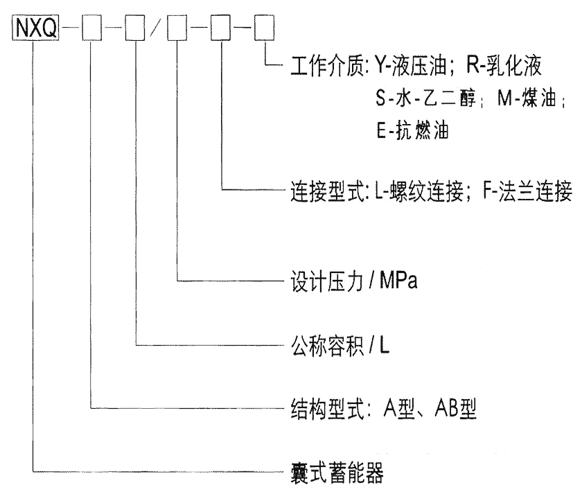
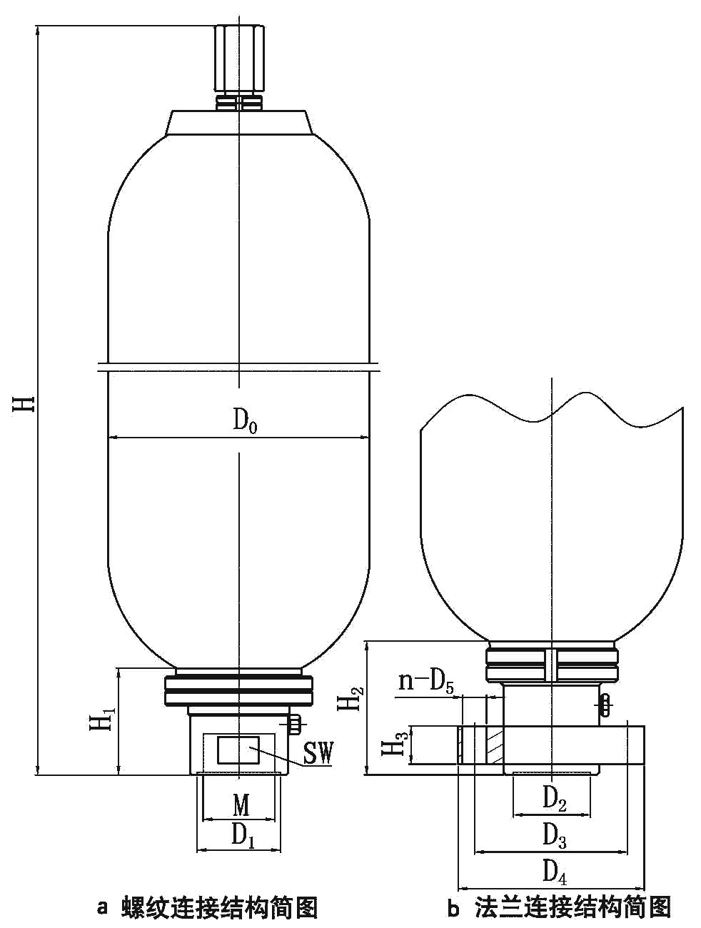
图1 蓄能器及型号示意图
3 特性
3.1 结构型式:A型、AB型。
3.2 固定方式:紧固环(抱箍)或支承座。
3.3 安装方式:原则上垂直安装。
3.4 工作介质:石油基液压油、乳化液、水-乙二醇、煤油、抗燃油等。
3.5 工作温度:-40℃~+120℃。
3.6 蓄能器气腔:充装无氧的干燥氮气。
4 囊式蓄能器使用和维修注意事项
4.1 使用单位应配备具有压力容器专业知识、熟悉国家相关法律、法规、安全技术规范和标准的安全管理人员,负责蓄能器的日常管理工作。
使用单位严格按照本产品使用说明书规定充装介质。
4.2 螺纹转换接头:螺纹接头与进油阀连接时应注意拧入端内孔尺寸不能太小,以防止阀杆顶住接头卡死,造成胶囊夹破(见图2接头示意图)。
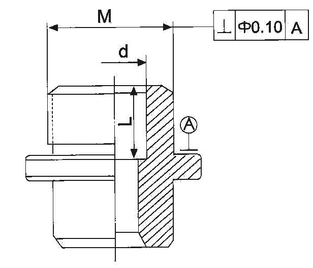
图2 接头示意图
接头的建议尺寸如下表:
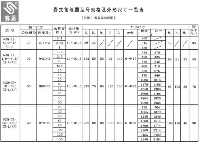
| 公称容积(L) | 壳体外径D0(mm) | 阀体连接螺纹M(mm) | 接头内径d(mm) | 内孔深度L(mm) |
| 0.4、0.63、1.0 | Φ89 | M27×2 | Φ16 | 18 |
| 1.6、2.5、4.0、6.3 | Φ152 | M42×2 | Φ22 | 30 |
| 10、16、20、25、32、40、50 | Φ219 | M60×2 | Φ25 | 40 |
| 25、40、50、63、80、100、120、150 | Φ299 | M72×2 | Φ30 | 50 |
4.3 充气、卸气注意事项
4.3.1 使用专用充气工具(见图3 充气工具示意图)。型号、压力范围和精度等级如下表:
| 型号 | 压力范围(MPa) | 精度等级 |
| CQJ-16 | Y-60、P=0~16 | 1.5 |
| CQJ-25 | Y-60、P=0~25 | |
| CQJ-40 | Y-60、P=0~40 |
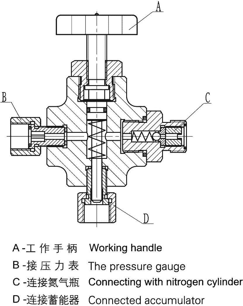
图3 充气工具示意图
4.3.2 充装气时,必须徐徐开启氮气瓶阀门,以便缓慢充气,确保胶囊在充气时不因充气速度过快而使胶囊损坏。当气源压力高于蓄能器最大允许工作压力时,应当在气源出口和充气工具之间连接减压装置,减压装置应配备2块压力表(一个高压表进气用和一个高压表出气用、低压调节旋钮、关闭装置和整体减压装置。
4.3.3 蓄能器严禁充装氧气、压缩空气或其他可燃、氧化性气体,否则极易引发爆炸。
4.3.4 气体侧的卸压:使用专用的充气装置安全地打开充气螺钉或充气阀以进行部分的释放或完全释放充气压力。
4.4 蓄能器充气压力与系统工作压力
4.4.1 状态参数的定义:
P0 = 充气压力;P1 = 最低工作压力;P2 = 最高工作压力
4.4.2 预充压力的极限值:P0 ≤ 0.9P1 工作压力P2 ≤ 3P1。
4.4.3 允许的压缩比为:P2 : P0 = 4 : 1。
作蓄能用,推荐:P0=65%~90%P1;
作缓冲用,推荐:P0=90%P(平均工作压力);
作消除脉动用,推荐:P0=60%P。
4.5 囊式蓄能器组装(见图4 NXQ-A型囊式蓄能器组装示意图)
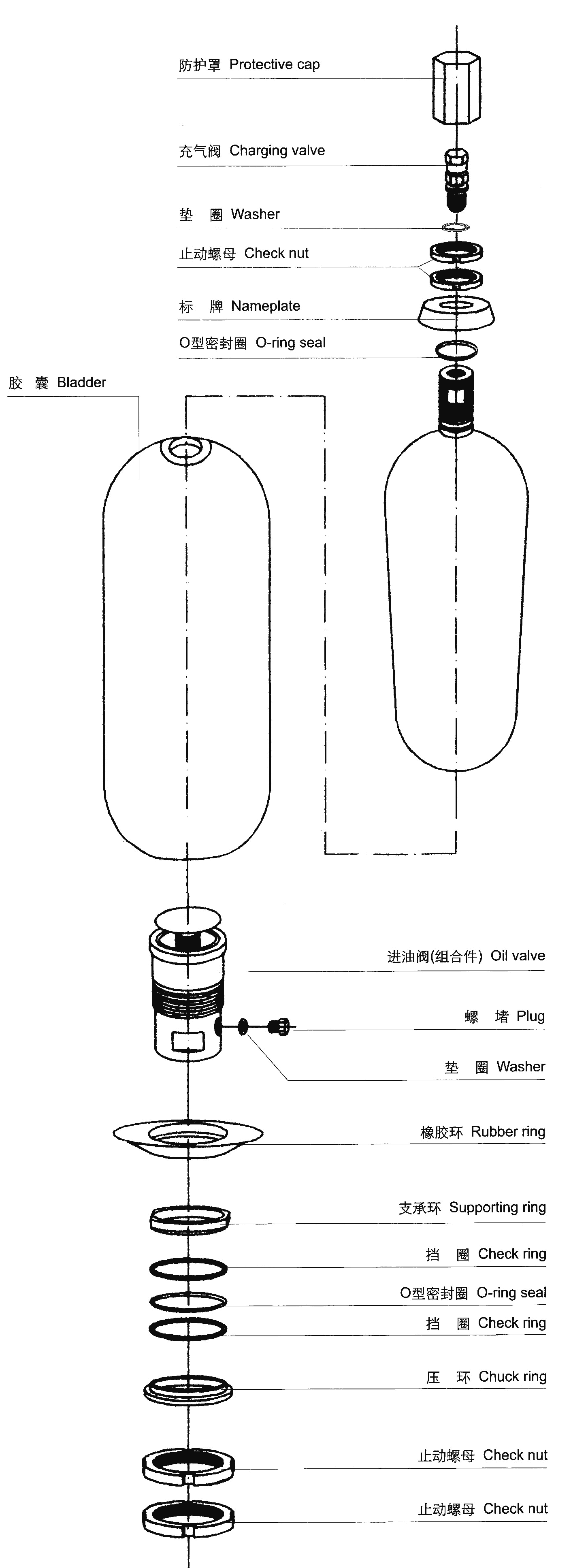
图4 NXQ-A型囊式蓄能器组装示意图
4.6 维修时注意事项(本产品为压力容器,拆卸和组装原则是由专业人员作业或在专业技术人员指导下进行。)
4.6.1 液压侧卸压:在拆卸蓄能器之前应将蓄能器的液压系统关闭或断开回路,卸去油压。
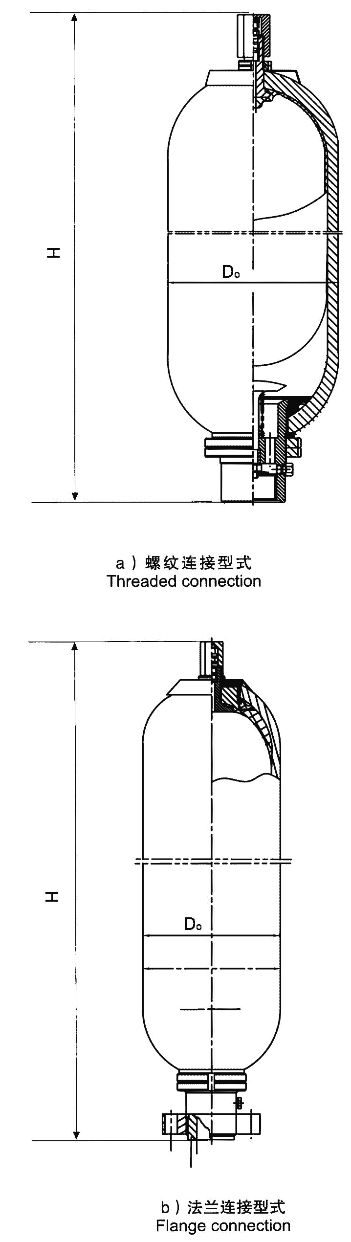
图5 A型蓄能器结构
4.6.2 压力释放时,相关压力表显现无压力方可拆卸。具体拆卸步骤详见图4 NXQ-A囊式蓄能器组装示意图。(见图5 A型蓄能器结构)、AB型蓄能器(见图6 AB型蓄能器结构)
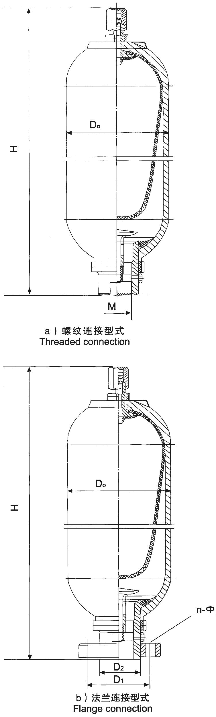
图6 AB型蓄能器结构
4.6.3 根据蓄能器结构特点,不论是A型还是AB型的进油阀装配,都是先将进油阀体、橡胶托、支承环等先塞入壳体内,并在壳体内依次将橡胶托、支承环装在阀体,再将阀体出口端拉出壳体外,一次装配。
4.7 蓄能器安装及检查
4.7.1 蓄能器宜充气阀朝上竖直安装,牢固地安装在固定支架或壁面上。
4.7.2 不得对蓄能器进行焊接的方式固定。
4.7.3 使用前对蓄能器安装及固定进行安全检查。
4.8 投用后的检查和维护
4.8.1 应定期对充气压力进行检测。皮囊及密封件2-3年定期更换。
Bladder Type Accumulator Instruction
(English version)
1 Application
Accmulators can be used in hydraulic system as pulsation dampeners,surge controllers,shock absorbers,emergency power,etc.
2 Notion of model
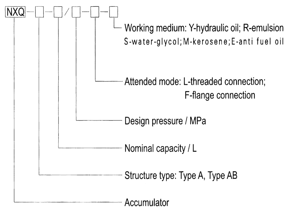
Figure 1 Diagram of accumulator
3 Characteristics
3.1 Structure type:Type A,Type AB.
3.2 Root:Fixed ring or support frame.
3.3 Installation form:Normally used in vertical direction.
3.4 Working medium:Hydraulic oil,emulsion,water-glycol,kerosene,fire resistant oil and etc.
3.5 Working temperature:-40℃~+120℃.
3.6 The air chamber:Need pure nitrogen without oxygen.
4 Cautions for using and repairing
4.1 There should be security administrator who is familiar with professional knowledge of pressure vessel and the laws,rules and standards about.
User should do charging according to the Instruction strictly.
4.2 The interior diameter of joint connecting with the oil port can not be too small,or it may stop the poppet and tear the bladder(As shown in Figure 2 Diagram of joint).
Figure 2 Diagram of joint
The suggestion dimensions of joint are as follows:
| Nominal capacity(L) | External dia. of shell D0(mm) | Joint thread of oil port M(mm) | Interior dia. of joint d(mm) | Depth of inner hole L(mm) |
| 0.4、0.63、1.0 | Φ89 | M27×2 | Φ16 | 18 |
| 1.6、2.5、4.0、6.3 | Φ152 | M42×2 | Φ22 | 30 |
| 10、16、20、25、32、40、50 | Φ219 | M60×2 | Φ25 | 40 |
| 25、40、50、63、80、100、120、150 | Φ299 | M72×2 | Φ30 | 50 |
4.3 Cautions for charging and discharging
4.3.1 Please use special tool for charging. The model,pressure range and accuracy class of charging gas tool(As shown in Figure 3 Diagram of changing gas tool) are as the bellow table:
| Model | Pressure range(MPa) | Accuracy class |
| CQJ-16 | Y-60、P=0~16 | 1.5 |
| CQJ-25 | Y-60、P=0~25 | |
| CQJ-40 | Y-60、P=0~40 |
4.3.2 It must be slow to open the valve of nitrogen cylinder and charge gas.It should connect the pressure reducing device with two pressure gauges between nitrogen source and chargetool when the pressure of nitrogen source is higher than the maximum working pressure of accumulator.
4.3.3 Charging oxygen,air,combustible gas or oxidizing gas is strictly prohibited.
4.3.4 Discharging:Open the valve or screw of chargetool to release pressure.
4.3.5 Charging gas pressure is according to working pressure and conditions.
4.4 Charging gas pressure and working pressure
4.4.1 Definitions of working parameter
P0 = Charging gas pressure;P1 = Minimum working pressure;P2 = Maximum working pressure
4.4.2 Limit of Charging gas pressure:P0 ≤ 0.9P1 P2 ≤ 3P1。
4.4.3 Permitted compression ratio:P2 : P0 = 4 : 1。
Recommended as emergency power:0=65%~90%P1;
Recommended as surge controllers:P0=90%P(平均工作压力);
Recommended as shock absorbers:P0=60%P。
4.5 Bladder accumulator assembly(As shown in Figure 4 NXQ-A bladder type accumulator assembly schematic drawing)
Figure 4 NXQ-A bladder type accumulator assembly schematic drawing
4.6 Cautions for repairing
4.6.1 It is necessary to release oil pressure before disassembling.
4.6.2 The oil port and bladder can be disassembled and assembled from the bottom during repairing for Type A accumulator(As shown in Figure 5 Structure of Type A accumulator).
Figure 5 Structure of Type A accumulator
4.6.3 The oil port and bladder can be disassembled and assembled from both ends respectively during repairing for Type AB accumulator (As shown in Figure 6 Structure of Type AB accumulator).
Figure 6 Structure of Type AB accumulator
4.6.4 Installation order is as follows whether Type A or Type AB.First put the oil port,rubber tray,supporting ring,and so on into the shell.Assemble the rubber tray and bearing ring onto the oil port interiorly,then pull exit end of oil port out from the hole.
4.7 Mounting and inspecting
4.7.1 Accumulator should be mounted on the bracket or wall vertically with gas valve upward.
4.7.2 Welding for mounting is strictly prohibited.
4.7.3 It is necessary to check the safety of mounting before working.
4.8 Check and maintenance when working
4.8.1 Check the gas pressure regularly.
4.8.2 Replace the bladder and seals in every two or three years.